LibreCAD Isometric Projection Drawing
Even though LibreCAD is a 2D CAD program, it doesn’t mean that everything you can draw is solely going resemble a single flat surface. LibreCAD, along with many other 2D CAD programs, let you switch from an orthogonal grid to an isometric grid. Other than those two projections, other CAD software, such as QCAD, allows you to have planometric, dimetric, cabinet, and cavalier projections. Learn more about QCAD with our LibreCAD vs QCAD post.
With an isometric grid, you draw a rendering of your two-dimensional drawing, still in two-dimensions, but with the appearance as if it was in three-dimensions. This is useful with complex drawings where there are a lot of overlapping and hidden lines. Even with basic parts, it can greatly help manufacturers mold the correct component.
Enabling the Isometric Grid
Drawing in isometric requires you to switch your grid. Actually, you can get away without switching the grid layout, but doing so makes snapping useful and you can more easily understand the projection. All this does is change how the grid appears and the snap points. No changes will be made to the actual drawing.
- Navigate to “Options” > “Current Drawing Preferences”.
- Switch to the “Grid” tab.
- Change the radio buttons to be “Isometric Grid” instead of “Orthogonal Grid”.
The grid should now have lines at 30°, 90°, 150°, 210°, 270°, and 330°. Each immdiate dot from the axis appear at those same angles. With each subsequent dot having their own dots at those angles as if the dot is the axis.
Quick Dive into Isometric Projection
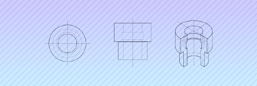
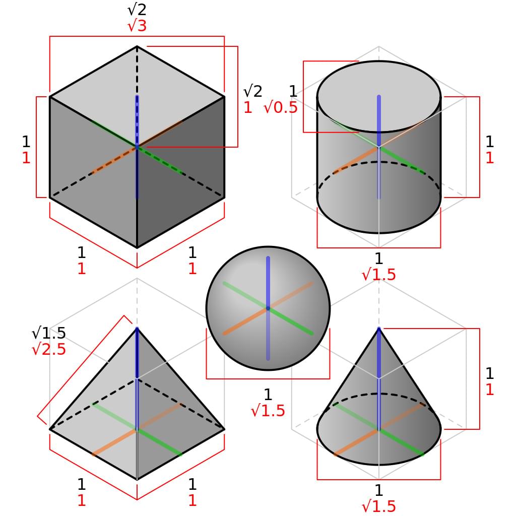 A cube, sphere, pyramid and cylinder in isometric projection.
Isometric projection is just a representation of a three-dimensional drawing. The lengths and dimensions in this projection will not match the true dimensions. Lines on the 30°, 90°, and 150° angles, which represent the front and side views, should match with the actual drawing. Measurements at other angles will not be what’s expected in an orthogonal drawing.
The “front view” or X,Y plane can be illustrated by drawing a line at 30° from the axis, and a line at 90° from the axis. The “left view” can be illustrated by drawing a line at 150° from the axis, and a line at 90° from the axis. These lines should represent the true length of the object, while other angles will not be directly related to the dimensions in your orthogonal drawing.
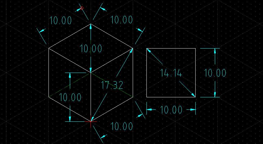
Due to how isometric projection is perceived, it has the limitation of not being able to tell the difference in height between two objects directly. You also will get dimensions that seem off if you don’t apply rotation to the measurements. For instance, with a cube drawing, both represent a 10x10x10 cube. The true diagonal dimension is 14.14, but in the isometric view the diagonal dimension appears to be 17.32 or 10.00 depending on which angle that you measure.
Reading the Isometric Projection Wikipedia article will likely give you a much better understanding about isometric projection. I know enough about the projection to draw in it but not enough to explain the entire concept well enough for someone new to understand.
Polar Coordinate System
Drawing isometric projections are a lot easier when you know how to use the polar coordinate system. Instead of entering simple X,Y coordinates or relative coordinates from the last position, you’ll enter polar coordinates which is the distance and at what angle.
When drawing a cube in isometric projection, drawing the front of the cube, You’ll enter the following commands. The polar coordinate format is structured as length < angle. You can either have these drawn from the origin of the image or relative by specifying the @ symbol before the coordinates.
line
0,0
10 < 30
@ 10 < 90
@ 10 < 210
@ 10 < 270
Using polar coordinates, you should be able to draw your three views into the isometric projection without having to do too much additional math. Things start getting more complicated when you have arcs and diagonal lines though. You’ll have to calculate the projection for those.
Measurements
Not all measurements will return what you expect. The isometric view is more for illustrating the final product while the orthogonal views should show dimensions. With that said, the isometric view should still be drawn to the same dimensions.
If you do want to add measurements to your isometric view, use the “Angled” dimension tool. This will give you accurate dimensions on the border of the faces and lines parallel of them. Measurements of diagonal lines within those faces will not yield the correct measurement. Angled dimensions will also not work, since everything is projected backwards at 30°.
If you must have dimensions inside your isometric view using LibreCAD, there is a very time consuming way to do it and I highly recommend that you just don’t.
- Create an “Angled” dimension where you want it to be placed, even when the measurement is incorrect.
- Select the dimension that was inserted into your drawing.
- Go to “Modify” > “Explode”.
- Select the dimension text and delete it.
- Using the “Text” tool, create new text for the dimension ticks.
Since the lines aren’t connected, you can’t turn it into a polyline. If you want to group together these exploded lines, your only choice is to create a block. Again, this is something I don’t recommend since you’re going to end up polluting your block list.